Redshift Sink
Useful notes, tips & tricks regarding the Redshift renderer
TOC
- Unified sampling
- TDR delay
- Shading
- OCIO & ACES
- Lighting
- Global Illumination
- Rendering
- AOVs
- Proxies
- Attributes
Unified sampling
Redshift uses an Adaptive Unified Sampling engine to fire rays intelligently. This allows it to fire more samples at desired areas and it reduces the amounts of samples where it is not necessary. Properly optimizing this can lead to faster renders with less noise. This is controlled in several ways. You can also turn "off' adaptivity and use a pure brute force method which fires rays equally across every pixel in the image. This is done by making all Local Samples 1 and making the min/max the same. Its not efficient and slow using that method because you lose all the advantages of Redshift's intelligent adaptivity We will be covering how the Unified Sampling Engine works behind the scenes to best optimize your settings and take advantage of the speed and quality benefits it provides.
To calculate how Redshift samples and how many "Primary Rays Per Pixel" it shoots you use a simple equation
This is important because Redshift cannot fire less than 1 primary ray per pixel. So if your Local Samples are less than Max Samples Redshift is forced to fire 1 Primary Ray. For example 256 Local Samples \ 512 Max Samples = .5, which means Redshift rounds up to 1. Using this knowledge we can then figure out how many samples per pixel are fired using another set of equations.
This now lets us know the bounding constraints the adaptive sampling engine has to work with. For example lets say you are using 16 Min Samples, 512 Max Samples and 1024 Local Samples.
1024 Local Samples \ 512 Max Samples = 2 Primary Rays Per Pixel
16 Min Samples * 2 Primary Rays Per Pixel = 32 Minimum Samples Per Pixel
512 Max Samples * 2 Primary Rays Per Pixel = 1024 Max Samples Per Pixel
This now lets us know the goal posts the Redshift adaptive sampling engine can use. It will fire anywhere between 32 - 1024 samples per pixel To increase the sensitivity of the engine you now can decrease the Adaptive Error Threshold. Lower numbers make it more sensitive to noise which causes it to fire more rays until it reaches the Maximum if needed. The default is 0.01
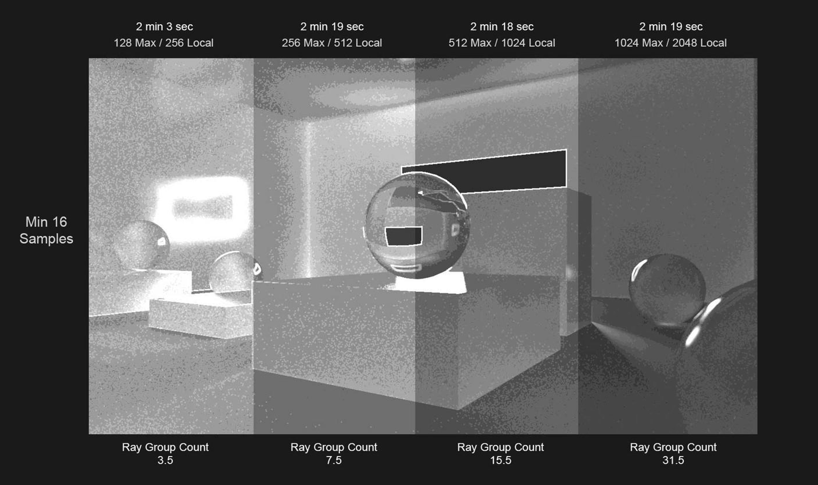
The "Show Samples" override lets us better visualize where the rays are being fired. The darker the area the closer to minimum rays fired, the lighter the closer to maximum. Notice how they all share the same areas where it fires less or more rays. The adaptive sampler error threshold is working the same way at 0.01 across all 4 images with a minimum of 16 samples. The only difference is that the overall gradient increases the higher the maximum it can go.
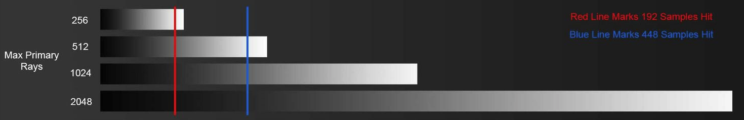
A way of thinking of this is as below. 4 gradients each doubling in size. The adaptive sampler stops firing rays in the same spot but because the gradient spectrum scale increases it falls on a different value but they all are technically cutting off at roughly the same ray count. This is why the render times are almost the same even when Max Samples is 1024 / 2048 Local. The Sampler is being intelligent and not firing more rays than needed. The reason it does increase render time slightly is because it is still firing extra rays in a few areas it feels it still needs like strong specular highlights and Anti Aliased edges.
Eventually for a static image with no DOF or Motion Blur you hit diminishing returns where your wasting rays. Typically you wont need more than 512 Maximum Samples for your upper bounds. When using DOF and Motion Blur you can easily require up 1025+ Max Samples to clean that noise.
There is also a hidden mechanic with the way Redshift groups sample workloads to the GPU. Redshift fires Rays in groups of 4 min, 8, 16 and 32 max. This process is called Ray Sorting. As Redshift renders a pixel it fires multiple Ray Bundles until the algorithm says stop. We will call multiple Ray Bundles "Ray Bundle Packets". The adaptive sampling engine analyzes each group bundle and decides whether to fire more samples or stop. So if you have low Ray Bundle Packets fired the adaptive engine has less information to work with leading to a decrease in speed and noise reduction. Redshift fires the minimum samples first and then continues to fire Ray Bundle Packets until it it decides its enough or hits maximum. An equation to find out how many Ray Bundle Packets is as follows.
This now lets us know the amount of Ray Bundle Packets Redshift sends to the GPU. For example lets use this example: 32 Ray Bundle (32 Min - 1024 Max Samples) = 31 Ray Bundle Packets. This means Redshift has 31 times to analyze the pixel and intelligently decide whether to stop firing rays or continue until reaching the Maximum Samples Per Pixel count.
So what if the Ray Bundle Packets are not whole numbers like 15.5? For example:
32 Ray Bundle \ (16 Min - 512 Max Samples) = 15.5 Ray Bundle Packets.
This means Redshift can fit 15 Ray Bundle Packets of 32 Ray Bundle sizes and then use smaller Ray Bundle sizes like 16, 8, 4 until it reaches the Maximum Samples Per Pixel count if the Adaptive Sampler needs that many.
32 Ray Bundle * 15 Ray Bundle Packets = 480 + 16 Ray Bundle = 496
Meaning it actually took16 Ray Bundle Packets, 15 Packets of 32 Ray Bundles and 1 extra Packet of a 16 sized Ray Bundle. If for example the 16 did not fit, it would step down to using 8 and eventually 4 as a minimum.
So in order to maximize the efficiency of each ray group you want Redshift to always fire 32 sized ray groups. You begin to have diminishing returns if your firing more Ray Bundle but using smaller Ray Bundle clusters like 16, 8, 4 instead of the full 32. 32 Minimum Samples Per Pixel which can be divided into the Maximum Samples per Pixel exponents of 32 evenly optimize the Ray Bundle Packets to use the MAX cluster of 32. This is important because if you don't have enough Ray Bundle Packets the algorithm wastes rays because it is unable to distinguish when to stop firing without enough packets. With enough packets (for static images 15-35 packets tend to be a sweet spot. You get faster noise detection and cleaner renders in less time. The adaptive sampler has enough packets of ray bundles to work intelligently even if your bounding constraints per primary ray fired are equal. The Ray Bundle Packet amount will alter how the adaptive sampler decides to fire ray samples. This is of course an ideal scenario, Redshift's Adaptive sampler can stop firing Ray Bundle Packets long before it reaches the full Maximum Samples and for the final Packets use smaller Ray Bundle sizes like 16, 8, 4.
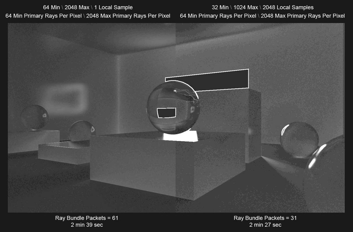
Below we have examples showing the differences between having more or less Ray Bundle Packets with your render times. Below both images have EQUAL amounts of Primary Rays Per Pixel. The range for the algorithm to work with between 64 Min 2024 Max are equal but the image on the right is using Local Samples to help the Unified Sampler. The image on the left has 61 Ray Bundle Packets which give smoother gradient transitions. But it is working harder and firing more rays across the board because it doesn't have as many dark spots as the image on the right, even though the image on the right has only 31 Ray Bundle Packets . This leads to the image on the right having faster render times because it is being intelligent about where it samples by firing less samples where they are not needed because the use of Local Samples makes the Unified Sampling engine work efficiently. The image on the left is having diminishing returns using that many Ray Bundle Packets.
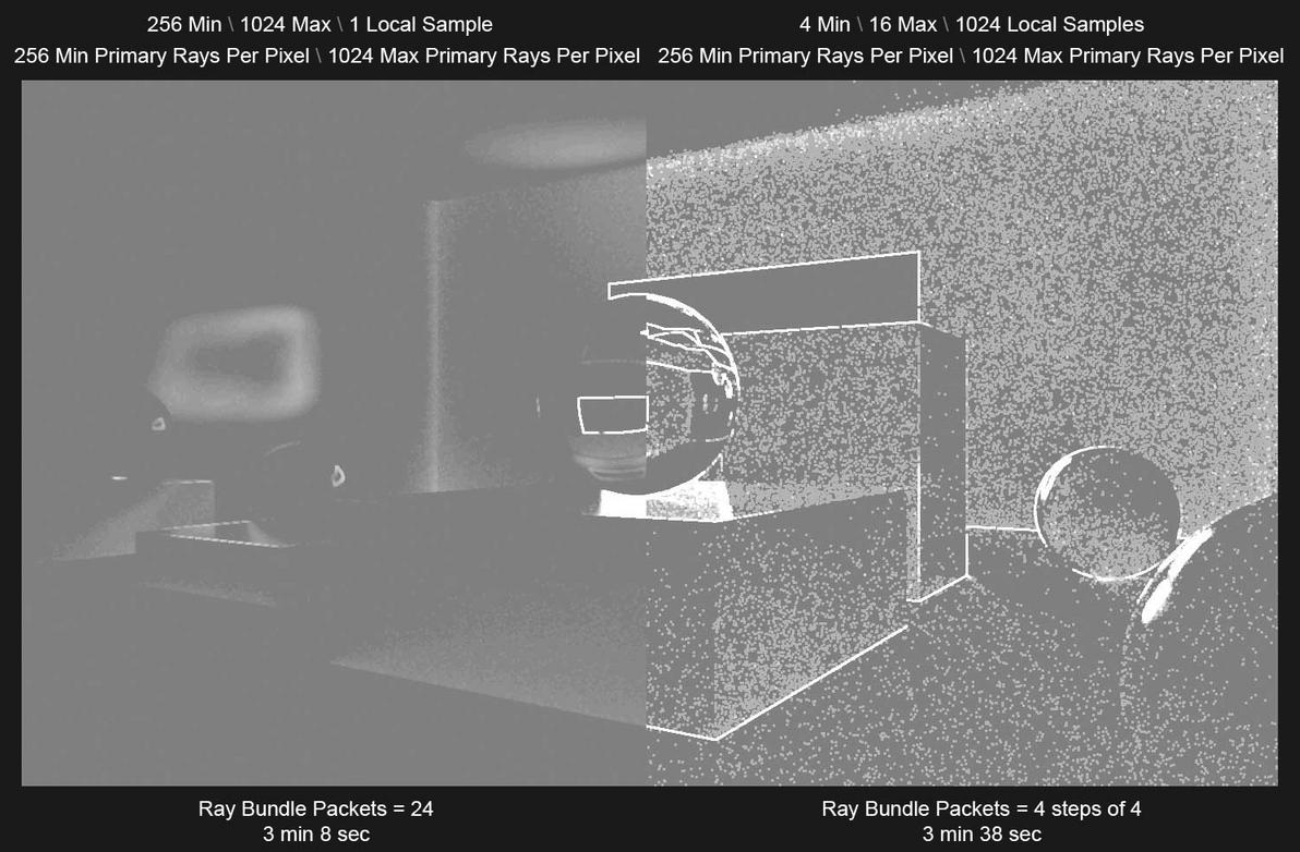
The examples below also have equal boundaries of 256 Min Primary Rays Per Pixel and 1024 Max Primary Rays Per Pixel. Even though the image on the left is not using Local Samples to help the Unified Sampler, it is still rendering faster because it is using 24 Ray Bundle Packets instead of the much lower 4 Ray Bundle Packets of the right. So even if the image on the right is using Local Samples to help the Unified Sampler, because it is using only 4 Ray Bundle Packets the adaptive sampling engine has difficulty with noise detection which increases render times.
TDR delay
TDR Delay in Registry:
Computer\HKEY_LOCAL_MACHINE\SYSTEM\CurrentControlSet\Control\GraphicsDrivers
Data value should be TdrDelay : DWORD 0x0000003c (60)
60 = being the seconds you need if its not (60), then double click on the TdrDelay text, change the input mode to Decimal and enter 60
Shading
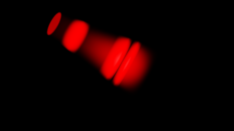
Light decay ramp
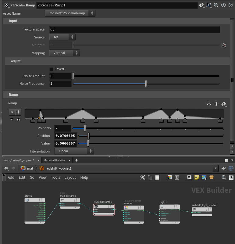
Realistic glass hacks
old material
- disable
cull dimm internal reflectionsunder theoptimizations tab - set
shadow opacityto 0.2 underadvancedtab - set the refraction/transmission color to something like
96% white, otherwise it's too transparent - add dispersion caustics and dispersion,
30-40looks good, but this will render slower - plug the bump details and reflection weight nodes into the shader for even more realistic appearance
- play with the
reflection end colorunder theadvancedtab: There you can choose between diffuse color or environment color. Diffuse color gives more black areas in the glass - make sure the glass intersects the table surface or the
IORbetween glass and surface will be incorrect
Redshift PBR mapping
Which map goes where for PBR, old material
IOR + Dispersion
Standard Material
the base mat IOR + abbe strength which can be whatever you want modulates the IOR to the correct Cauchy based output IOR
- Saul
Non Photorealistic Rendering
Non-PBR rendering, custom Lamber shading
Non Photorealistic Rendering using Redshift in Cinema4D
Reducing shader calls
"Material too complicated" message
Usually this problem comes from using a lot of triplanar nodes in the same material. Instead of using materials with triplanars use the triplanars to blend between inputs then end up with one bump, one displacement and one material, this should reduce the shading calls.
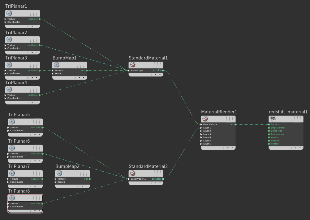
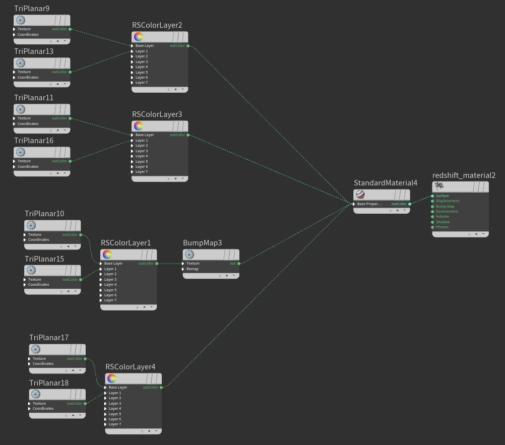
Left image - many calls, Right image - fewer calls
Normal vector output ranges
Red (-1,1)
Green (-1,1)
Blue (0,1)
OCIO & ACES
ACES output settings
To use the rendered image out of the box
View: ACES SDR Video
Compensate for View Transform: On
To apply the ACES at post so you can color correct with a wider range
View: Raw
Compensate for View Transform: Off
Not to do
It does not match the IPR rendered image either out of box or after post process
View: ACES SDR Video
Compensate for View Transform: Off
BUT also the docs say:
a logarithmic color space (ACEScct) or the raw linear result which is unaffected by the Display transform.
But this doesn't relate to the view compensation, it still does something nonsensical (for log and raw color spaces)
Lighting
Env vs. Sky vs. Dome contribution
It might look a bit different if GI is on as reflections are part of the GI
- Adrian
The dome light kills the environment lighting
- Catche
just use a giant sphere and enable / disable the RS Object properties you want. More control that way
- Saul
throw the texture into an incandescent material
- Catche
because of the order / precedence of the dome light vs physical sky what is contributed takes precedence over one and the other just due to the inherent hierarchy the infinite lights have on each other. Whether they can add some way to change that order as an option on these lights I don't know.
- Saul
Light Affected by refraction
Auto means at lower roughness refraction rays bend accurately (mostly noticeable with HDRI) and as roughness increases it switches to performance mode. Assumption being you can’t see the ray bending as roughness increases anyways. But there are scenarios where it matters more than others. Always means it’s always active but comes at the performance hit.
Light linking
Volumes do not support light linking
-Adrian
Global Illumination
GI guidelines
choosing the right Global Illumination mode for the case:
flat surfaces - IC
details, vegetation - BF
mixed situation - IC for main, BF for others using RS Object Tag
Rendering
Motion blur overhead
The transformations motion blur doesn't add any overhead to the scene extraction code, but you can indeed improve a bit the scene extraction time and the used GPU memory if you disable the mesh deformations motion blur in the static objects. Currently, the plugin doesn't do that automatically, but is a good research topic. I'll think about it.
- Juanjo Gonzales
Motion blur ROP vs Obj
The OBJ level frame duration is a multiplier of the ROP node frame duration, while the OBJ level shutter offset is added over the ROP node shutter settings. The OBJ level options don't replace the ROP settings, which are the same for all the scene objects.
- Juanjo Gonzales
Shadow Ray biasing issue
White lines on the creases
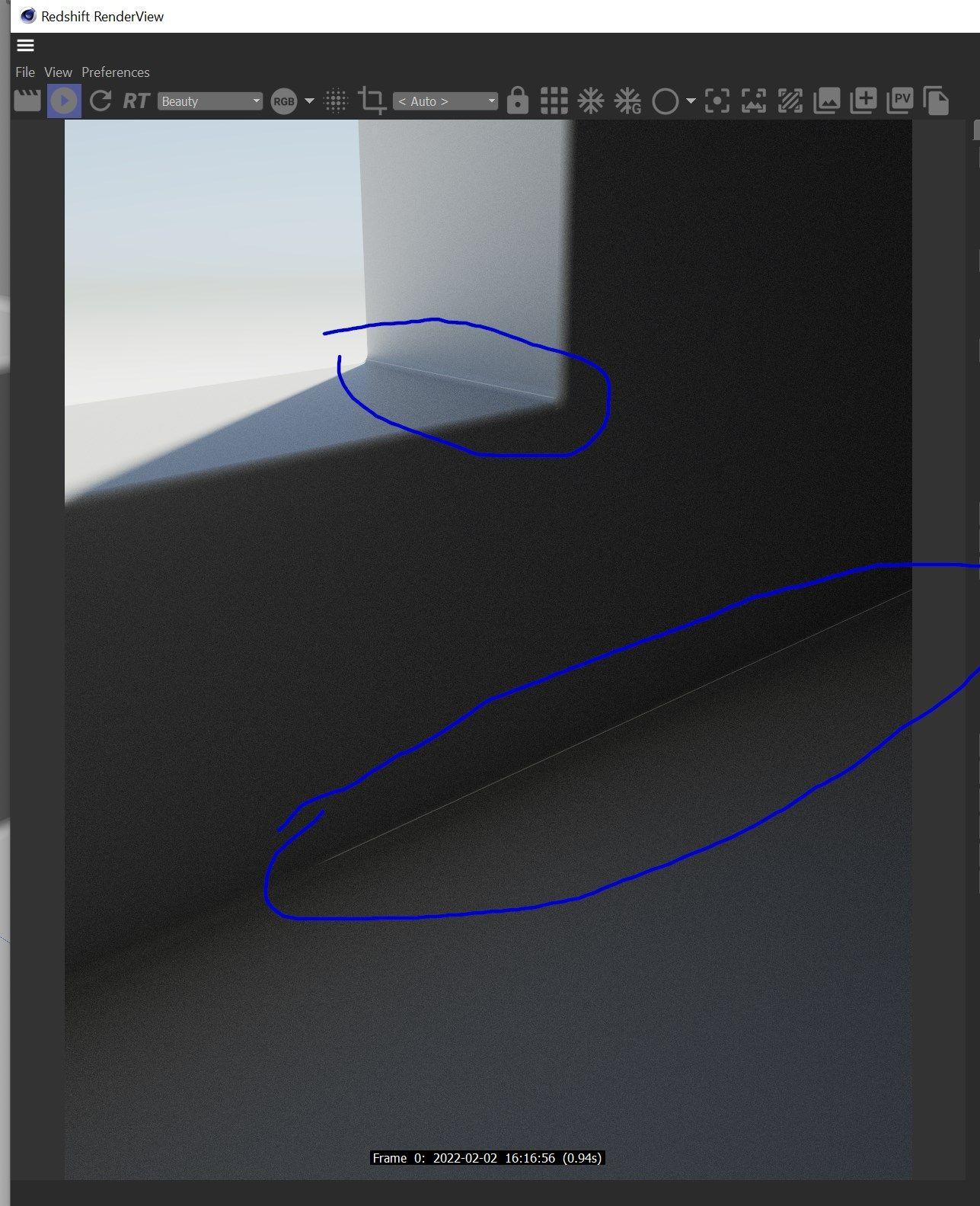
Solution: disable shadow ray biasing in the experimental options
Caustics vs bump
Source
Bump doesn't affect caustics
I believe this might be a limitation as the caustics are a point cloud compute so it happens before shading.
- Adrian
Photometric units
Photometric Units to Meter Scale
Certain features of Redshift such as photographic exposure, physical sun/sky and IES light support require knowledge of the "units to meter" and "candela to square meter" settings. It's important to set these values correctly, otherwise lighting coming from physical light sources might appear too dim or too bright.
If you're working with centimeters (i.e. 1 world unit is 1 centimeter), the units to meter scale should be set to 100. That's because, in this case, 100 world units means 100cm, which means 1 meter. If you're working with meters, then it should be set to 1, because 1 world unit means 1 meter.
cd/m^2 Factor
Photographic exposure, IES lights and the physical sky/sun use the cd/m^2 (candela to square meter) setting. Please make sure to attach a photographic exposure lens shader when using IES lights and physical sun/sky, otherwise your lighting will appear too bright or too dim."
Visible edges with SSS
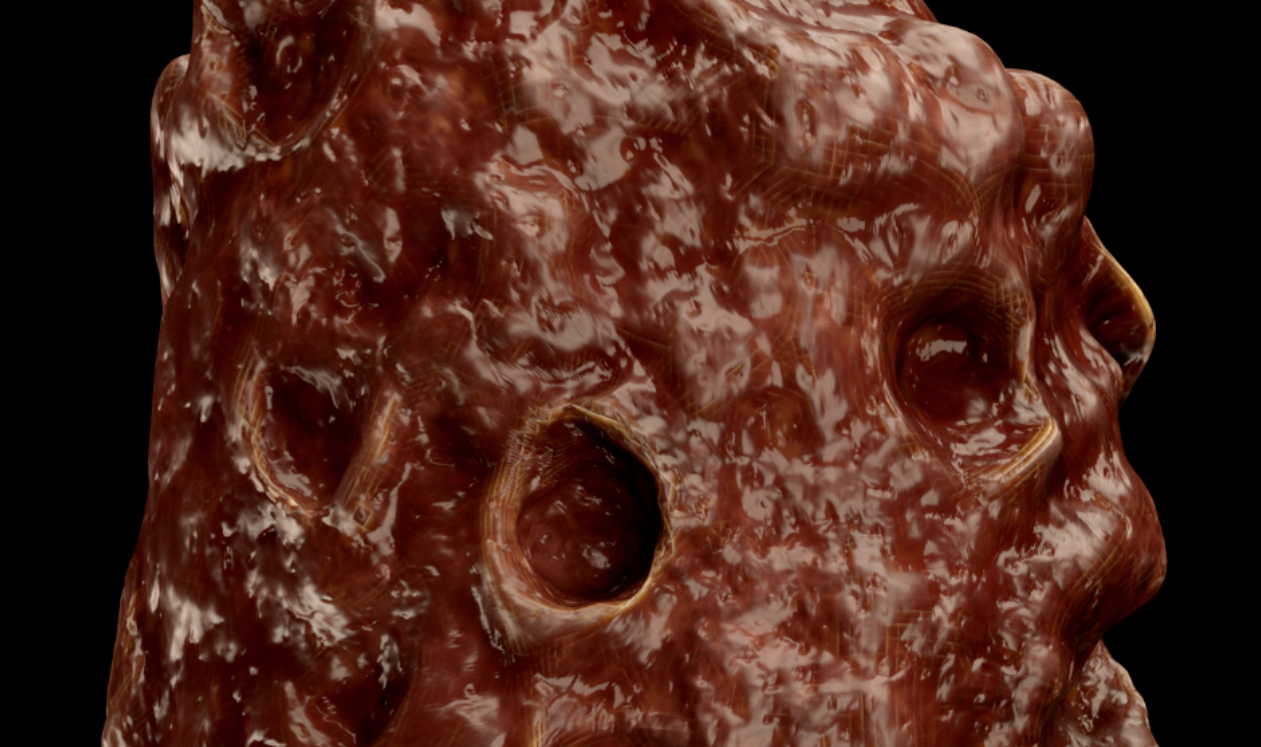
You need a bit more render tessellation as probably the radius of the SSS is bigger than the edge
- Adrian
AOVs
Custom AOVs
Custom AOVs in Redshift for Cinema4D
Custom AOV banding/artifacts on unclamped color data
So i was having consistent glitches and artifacts on various buckets, consistently on specific frames.
I traced the issue down to a custom AOV i was using to export a pass for a color map. This color map was probably above 0-1 values after a color correct node for contrast etc.
Once i set a change ranged after it(set to clamp) the issue was resolved
AOV Apply Color Processing
Enables or disables "Apply Color Processing."
The "apply color processing" option means that gamma correction (if gamma is other than 1.0) and photographic exposure (if a photographic exposure lens shader is present) will both be applied to the AOVs.
Matted objects do not work with the Diffuse Lighting AOV
Shadows that are normally visible in the Diffuse Lighting AOV will not be present for a matted object and you will need to color correct and multiply the background with the shadows/inverted shadows for the matted object.
The Diffuse Lighting AOV already includes a renders Translucency component
If you need to isolate the Translucency component from the Diffuse Lighting AOV please see the raw AOV workflow here
Proxies
RS proxies are tessellated, Not quads
A proxy holds triangles not quads, the mesh has been tessellated already, that option (the wireframe shader's) is to only show original non-tessellated edges which is not the case with a proxy
- Adrian
Attributes
Supported RS particles attributes
The sphere particles in Redshift only support one single scale value, so they only support the float @pscale or @width attributes. If you need particles with XYZ deformations, you are going to need to use point cloud instances, that support the vector @scale attribute.
- Juanjo Gonzales
Object rest position output
You need to output the rsState RayPosition into a custom AOV, with the rsState set to reference
String attributes
The string attribute cannot be passed directly to the Texture node, requires to use an OSL node instead
shader texName
(
    string myString="",
    output color outColor=0
)

{
    outColor = texture(myString, u, -v);
}
and then passed over like this:
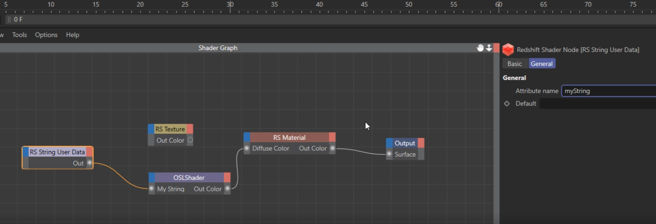
Mapping curve UV strands
By now the strands are not using the curve UVs at all
Promote primlength attribute to points and use for example with Maxon noise V scale